The different projects

2/28/13

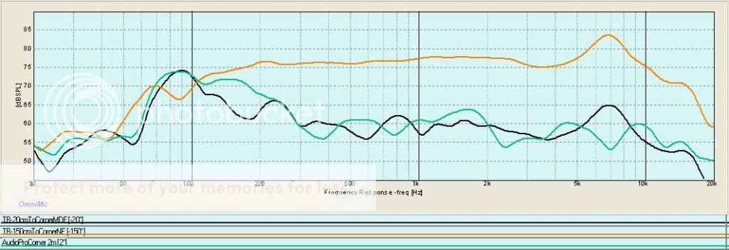
Frequency Responces (Dayton Omnimic near field)
At the first set of curves I had forgotten the tone controlls at full tilt, this was rectified for the second set. The calculated value was 800 µF but I measured the whole range. 0-2200µF


Notable features
Pivot point is at the resonance frequency no cap is black top trace.
Brown bottom trace is 200µF that reduce the 50-80 Hz hump a lot but also introduce a peak at 40 Hz very much as first order crossovers does (not) work with most dome tweeters.
The red trace for 400µF looks much better.
The jumps at 70 and 95 Hz is as of now unexplained.

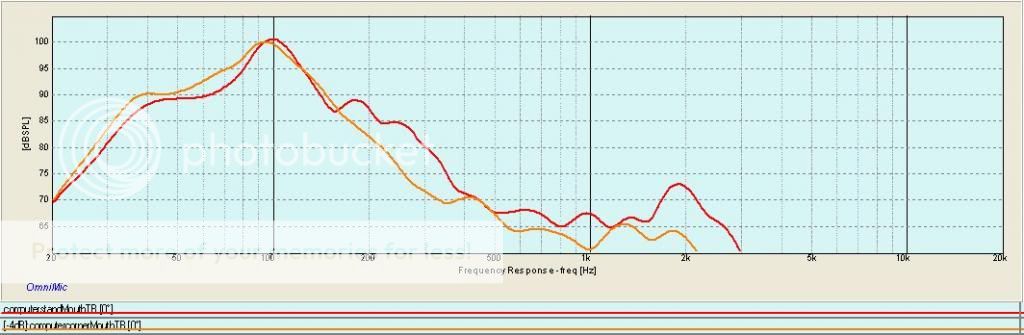
I the next set (with tone controls set at defeat) I focused on  what appears to be the most resonablce capacitance range 400-900µF in 100µF increments for clarity some of them is not included in the graph.
With the current setting 400-600 µF seems to be best, but with the crossover in place the Q will go up a bit so any final tweeking with regard to the size of the serial cap has to wait.
But these findings suggest that you can tame high Q drivers with serial caps. The peak caused by the to small cap could be explored in an open baffle speaker where the peak is set to compensate for the baffle drop off and then the rapid fall below that would protect the driver.

Time to tackle the crossover and the tweeter...

Dorspen One BC

Intro
This is a thinly veiled homage to the Spendor BC1. Main features of the BC1 is a thin-walled  cabinet with internal damping pads. Thin like 10 and 12 mm plywood and then 12mm bitumen loaded soft fibre board as damping pads.The idea behind the thin-walled design is that thin walls and damping brings down resonances from the critical midrange to the less critical bass range. A Bextrene driver with some midrange magic is added. That is has a super tweeter and is bass reflex loaded is secondary features. That the both front is removable and the lip around the front is tertiary featurers.

The spendor BC1 has no damping in the front baffle, I plan to have some bitumen board there as well


Material and Methods
The cabinet is quite close to the original 300x630x300 by just increasing the depth some. 11mm OSB was used instead of 12 and 10 mm Plywood, internal damping is by bitumen impregnated softboard as per the original. All inner surfaces is lined with 10mm felt. This might seem to be odd in a closed box but the thing is that experiments published by Hobby HiFi has shown that gluing felt on top of other damping material is a synergistic icing on the cake! As in the original the front is removable and the bassdriver is rear mounted. In my case to hide the very ugly frame.
The KEF B200 I have has a ugly metal chassi, showing when front mounted and rear-mounted there is a lip about 3 mm running along the the perimeter making a proper seal tricky and also minimizing the contact area with the cabinet.

Bassdriver is a a KEF B200 SP1014 as the Spendor driver it has a to high Q to fit in any reasonable bass reflex box. A closed box is viable but a bit boring. One option us to use Dynaudio Variovents to lower the Q as I have a couple of those left over. Then I read in the excellent magazine Hobby HiFi about using a large serial cap to lower the Q and F3 of the system.
 

Calculation Corner
First one has to calculate how much the Q is affected by the resistance of the coils in the crossover
Qes*=Qes x(Re + Rv )/Re
Then you can calculate the new total Q
Qts*= 1 /( 1/Qms + 1/Qes* +1/Qb) with the box Qb being in the order of 10-20.

With that in the bag it is time to calculate the needed box volume. The Q to aim for is 1.0 for common drivers, 1.1 for drivers with very low inductance and 0.9 for high inductance drivers

So the box volume is
Vb= Vas / (Qtb/Qts*)2 -1

Then it time to calculate the size of the capacitor. There is a constant K that is dependent of the inductance of the driver. A normal driver use K= 265 000 with low inductance the value is 316 000 and really high inductance drivers 100 000

C= K x Qts*/ (Re x Fs)

F3 =  0.7 x Fs/Qts*
For a more theoretical work there is JAES Volume 58 Issue 7/8 pp. 577-582; July 2010  by no other than the late great Neville Thiele (like Thiele Small parameters)


With a high Q resonance there is too much output at the hump above the resonance frequency and too little below the resonance. The theory is by adding a cap of the right size the cap will interact with the resonance peak and increas the impedance above resonance ( reduce the hump) and decrease impedance just below resonance and thus increase output over a limited range. At even lower frequencies the cap will increase the cut off slope by 6 dB and add protection to the bass driver.

In the case of my KEF drivers I end up with a 67 L enclosure and a cap of 800µF (The final value will vary with resistance of any coils in the crossover in series with the driver) for a Q of 1.0 an a Fc of 49 Hz., I cheat a bit and use a smaller box  of 350x700x350 mm that has an internal volume of about 58 L and hope that the stuffing will make up for the lacking volume.  A way out would be to discard the cap and use variovents instead.
In a lightly stuffed box I got a Fs of 47 Hz and Q of 0.95 not bad at all, this is with no crossover so with that the Q will become higher, in the final version but I wanted to try out the concept.

I have a collection of 100µF caps made in West-germany, 22 of them so time to test some combinations.


Results (so far)
Here I test from 0 to 2200 µF mostly in steps of 400µF
And more in detail with regard to increase and decrease in impedance around the resonance
It looks to be in good agreement with theories and now I have to make accoustic measurements as well. For the final results I will have to rerun everything with the crossover in place, but I wanted to get a feel for how useful the technique of capacitor coupled closed box loudspeaker is.


2/15/13


The removable side wall was handy for changing damping material. However. there is a price to pay, even with me on top of the speaker the foam is enough to decouple the sidewall from the rest of the box, mechanically. This means most of the box walls and baffles have one long free edge that vibrate and change both output and impedance curves. My finding with the removable side wall was the I was better of with no damping in the pipe and only damping in speaker chamber and IHR.

Now for some corner and room measurements.

To take room effects I have done like this:

1.Microphone 2 m from corner and at driver hight for the horn

2.Measure AudioPro 2.14Live speaker put in the corner of the room. It is a conventional good bass reflex 6.5" & 1"dome, large aberations are due to room not speaker

3.Put horn opening 150 cm from corner, the driver at the front is then quite close to the microphone.

4. Stepwise back the horn into the corner 80-40-20cm

Note that while one wall is a proper concrete wall the other that also is a concrete wall has a gyprock wall 10 cm in front of it
The first graph should be here but for some reason it ended up at the very top 3 times in a row.

Or with just the core curves


Top orange is near field (150cm out) dip at 90 and 40 Hz visiable.
Green is the Audiopro and black the Tangband King compact horn.
It looks good apart from the depression 120-200 Hz, if this is due to my deviations from Kings design or not is for others to elucidate.

How it sounds

In my living rom, side wall is a proper concrete wall, back wall is a flimsy thing, a similar wall with the Klipsch Corner Horn killed 6-8 dB below 80 Hz as I recall.
NAD 20 years of music (NAD and Sheffield Lab)
Not bad at all you clearly hear the kick drum and it suggest some weight, but the "slam" is missing. Higher up the the TB is really good, that peak at 7 kHz does not sound to bad unless you sit straigt on axis. Way better than the Philips 9710.

The Committments original soundtrack
Mustang Sally got me up and dancing
"Chain of fools" I can feel the bass both in the floor vibrations and in the backrest of the couch, that is darn impressive for a 4" driver. The previous horn I tried had 12" drivers that is 500cm2 instead of 50 cm2

So to conclude (my iteration of the design). It has surprising amount of bass that is dry and well defined not lumpy one note as I feared. The TB have quite a length of cone travel ( I can't stand the rain is really good, grin) with the Fostex that has far less and so the bass output and slam has to bee seen in it's context. In a 25m2 room (300 sqf) I can play quite loud and then the TB run out of steam without sounding harsh or strident.

Proper corners are important, I wish I had some!

I got some feedback that corner loading should affect impedance and mouth mesurements and to prove me right I measured impedance both in corner and free space and frequency response in horn mouth, this time in a true concrete corner. Really cramped with a large IKEA computer desk close by, but solid walls.

This is what I got


Identical curves below 70 Hz and above 130 Hz but between that more swings up and down in the 70-130 Hz range.

I then did the frequency response, and the corner mesurement is actually a bit different and better


So I wrong, thanks.

Now for the horn in proper concrete corner


Now it looks even better, the output in the 40-30 Hz range is better than other loudspeaker. The are not completly matched, with the bass reflex and horn opening close to the corner the AudioPro Woofer is 40 cm from the corner and about 25 off the floor. The Tangband is a full meter from the corner and 75 cm or so off the floor, so they may add upp differently.

A brief listen confirm previous findings, deep bass is there but the slam is not there but I guess that you simply need more cone area to get that effect.

I do recomend anyone with small fullrange drivers to give this design a try, thank you so much Mr King for this little gem! Time to get some IPA. (Fuller Indian Pale Ale this time)